BEAs UL LISTED MAGLOCKS provide a standards compliant locking solution for retail healthcare banking and other high security facilities that require UL Listed security products. 1200 UL MAGLOCKS USERS GUIDE ELECTROMAGNETIC LOCK 1 Description The Electromagnetic Lock Maglock series is a surface mounted magnetic lock assembly.
 Bea Maglock Wiring Diagram Automotive Alternator Wiring Diagram Begeboy Wiring Diagram Source
It shows how a electrical wires are interconnected which enable it to also show where fixtures and components might be connected to the system.

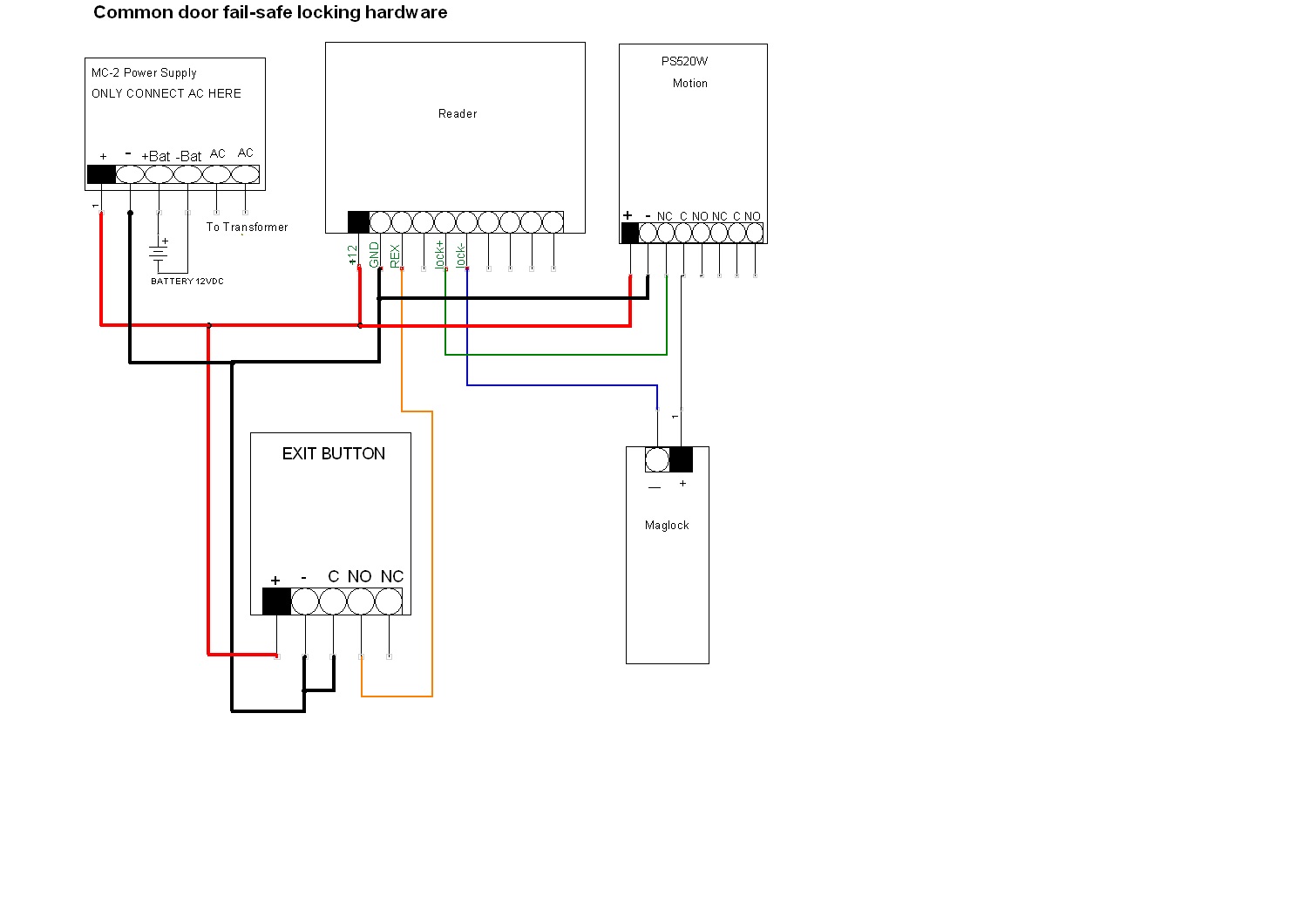
Bea maglock wiring diagram. A 1200 lb pressure-sensing maglock is coupled with a keyswitch and sounder to create an easy-to-install solution that controls and monitors door access. It reveals the components of the circuit as simplified forms and also the power and also signal connections between the tools. BEA product documentation library containing product user guides cut sheets application notes architectural specifications wiring diagrams and brochures.
The features to consider during the installation procedure. This will conver t the AC to DC. The mounting diagram is NOT a scaled template.
Read Or Download The Diagram Pictures Maglock For FREE Wiring Diagram at BURROWDEMOAGRIYACOM. DESCRIPTION 10MAGLOCK1UL 10MAGLOCK5UL Lock Single Double. MAGNETIC LOCK WIRING INSTRUCTIONS MODELS 600S 600L 600D 1200S 1200L To remove the header plate it may be necessary to remove the wiring compartment screw.
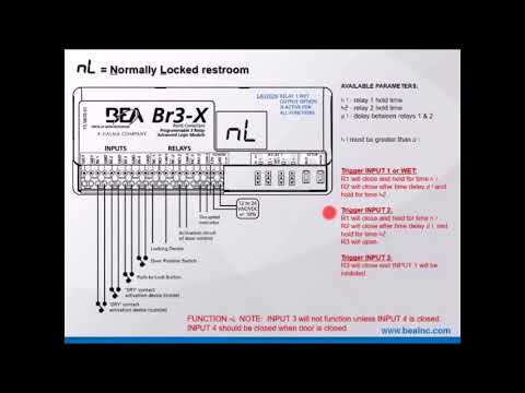
- WIRING INSTRUCTIONS Magnetic lock or fail safe strike with button keypad maintained button and remote receiver. The delay on break timer will release the lock and then the delay on make timer will enable the door to open and be held open for a set period of time. Read Or Download The Diagram Pictures Maglock For FREE Wiring Diagram at CROWDFUNDING-DONATEDEMOAGRIYACOM.
Sensing systems that count record and analyze pedestrian traffic flows to maximize the efficiency of a buildings setup and ensure that inventory placement is maximized. It starts at the positive terminal of the power supply travels through the exit and entry switches into the positive terminal of the magnetic lock and out through the negative - terminal of the mag back in through the negative terminal of the power. Use the template diagram installation instructions included with the DM62 Magnalock assembly.
The 46304630 operator has a 12 VDC and 24 VDC output that can power an electric strike or maglock. The kit meets a variety of building fire and life safety codes. Wiring the Electromagnetic Locking System.
The E600 Series magnetic lock is mounted to the underside of the header on the stop side of the door. ASSA ABLOY the global leader. The mounting diagram measurement and marking placement are critical.
In the simple diagram above you can see that the electricity travels in an unbroken loop. If this is not available you may use an AC power source and wire inline a Full Wave Bridge rectifier. Wired in series Power Supply for fail safe strikes and magnetic locks should be DC.
BEAs DELAYED EGRESS MAGLOCK KIT is a user friendly security solution for out-swinging perimeter doors. A long wiring compartment screw can be used to increase security by limiting access to the header plate mounting screw from below the lock. A wiring diagram is an easy visual representation with the physical connections and physical layout of the electrical system or circuit.
Position the Magnalock centered between the doors. Sensing systems that count record and analyze pedestrian traffic flows to maximize the efficiency of a buildings setup and ensure that inventory placement is maximized. Locknetics maglock wiring diagram What is a Wiring Diagram.
It is perfect to use when either a magnetic lock or electric strike is installed on an automatic door. Read Or Download The Diagram Pictures Maglock For FREE Wiring Diagram at CROWDFUNDING-PLEDGEDEMOAGRIYACOM. 10MC25 is a delay on make delay on break time delay.
Its components are shown by the pictorial to be easily identifiable. The wiring diagrams are shown on page 14 of the installation instructions attached. A wiring diagram is a streamlined standard pictorial depiction of an electrical circuit.
Available in single and dual lock varieties and various sizes force designed for standard installation on most types of doors. BEA Products Accessories. An inswing mounting kit optional can be used when mounting on the hinge side of the door.
Is the least efficient diagram among the electrical wiring diagram. Assortment of locknetics maglock wiring diagram. Maglocks can be used on hollow metal wood aluminum glass and composite door materials.
Industrial Air Horn Schematic It is far more helpful as a reference guide if anyone wants to know about the homes electrical system. PINSTALLATION INSTElectromagnetic LocksEXCELINST-E600vsd REV A3 05-18 Page 1 Any suggestions or comments to this instruction or.
Https Www Beainc Com Wp Wp Content Uploads 2017 04 75 5702 04 Delayed Egress Maglock 20180419 Pdf
 Br3x Youtube
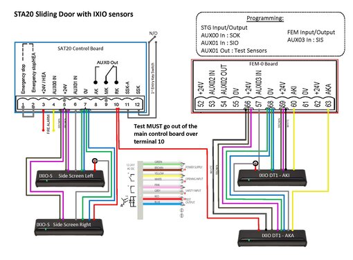
 Electric Magnetic Lock For Automatic Sliding Doors Sanway Technology Automatic Sliding Doors Magnetic Lock Sliding Doors
 Br3 Rd433 Non Ul Manualzz
 Navigation Navigation Products Training Videos Contact Us My Record0 Documents Videos Case Studies Techie Top Tips Diamond Partner Program Bde Tool News Careers About Record Direct Warranty Supply Only Order Forms Products Accessories